Let’s talk about Color Spaces, Levels and Ranges.
Levels Ranges & Mapping Schemes
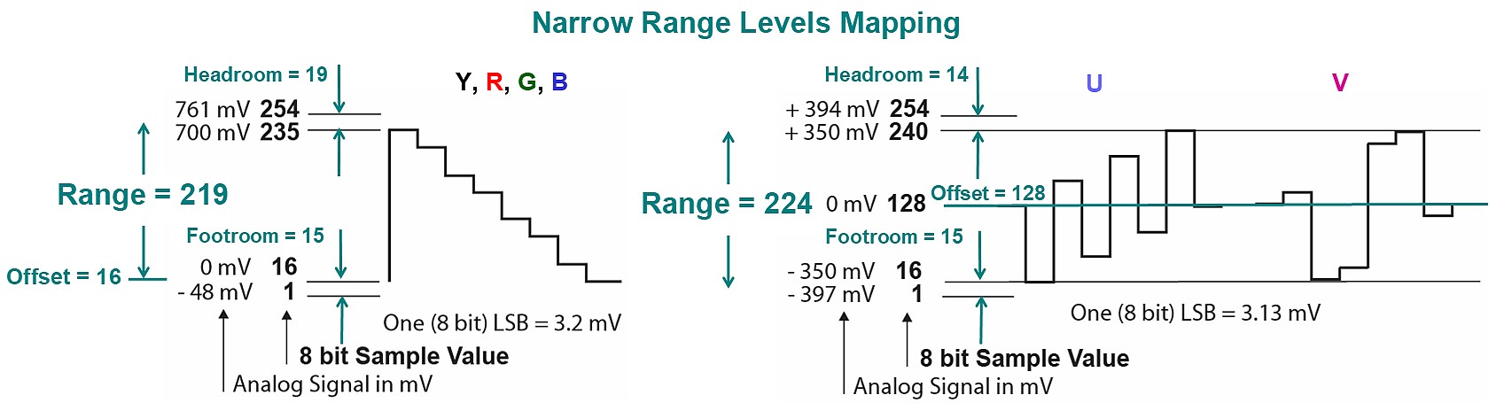
In broadcast environment RGB (and Y) values are conventionally shifted and scaled to the range [16, 235] referred to as
“Narrow Range” = “NR” (aka “Limited Range”, “Low RGB”, “TV“, “Broadcast”, etc.).
In 8 bit representation the boundaries of this range are [16, 235] , in 10 bit they are [64, 940], in 12 bit [256, 3760] and so on.
Thus, for digital 8 bit RGB and Y data:
- Reference Black Level is 16 (64 on 10 bit scale),
- Reference White Level is 235 (940 on 10 bit scale)
The headroom above 235 and the footroom below 16 accommodate signal overshoots (“ringing”) due to filtering and specular highlights.
The U & V signals are just scaled versions of Color Difference signals B-Y and R-Y, so they are bi-polar by definition.
To fit the available [0, 255] range UV signals are centered (after scaling) at mid-range point 128.
Thus, for UV signals Reference White Level = Reference Black Level = 128 (512 on 10 bit scale).
In broadcast environment levels from 1 to 254 are available for video, levels 0 and 255 are used exclusively for SDI interface synchronization.
 YUV Narrow Range Levels
The [0, 255] range referred to as “Full Range” = “FR” (aka “High RGB”, “PC“, “CG”, etc) is also widely used for digital RGB interfaces, e.g. HDMI.
For YUV signals the Narrow Range ( [16, 235 Y], [16, 240 UV]) is mandatory; some consumer product use non-standard ”yuvj” [0, 255] color space.
In file based environment all levels from 0 to 255 are available for video (NR and FR) – because there is no need to reserve levels 0 and 255 for synchronization purposes.
To avoid possible confusion, due to the plurality of mapping schemes and bit ranges, the international standardization bodies prefer relative levels schemes (also used in this post for all math expressions and coefficients):
For Y and RGB: Black = 0, White = 1,
and there is no “legal” levels beyond these limits
For UV: Black = White = 0, Min Limit = -0.5, Max Limit = +0.5.
RGB ⇔ YUV Conversion Matrices
Fundamental RGB to Y conversion coefficients (single column matrices) are defined by the international standards:
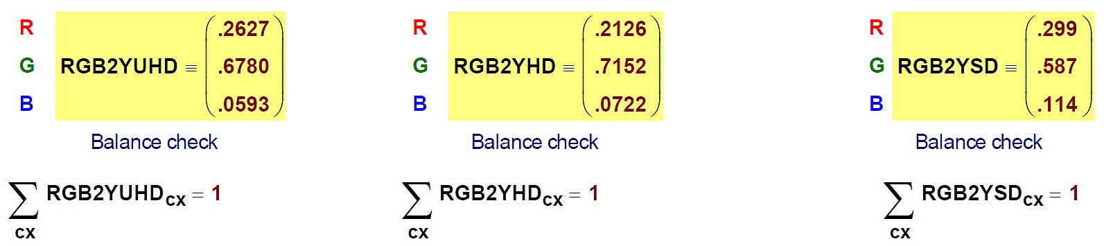
UHD in the matrix label means two standards:
BT.2020-NCL (UHD-SDR),
BT.2100-NCL (UHD-HDR & HD-HDR),
HD means BT.709 and SD means BT.601 standard.
All matrices are balanced, i.e. the sums of their coefficients = 1, so the R = G = B = 1 (100% white) input produces Y = 1 (max Y value) output.
For practical applications the RGB to Y gain factors should be rounded to the appropriate bit depth, and it is very important to keep Unity Gain principle (sum of 3 coefficient must be exactly 1).
The following RGB ⇔ YUV matrices are just math derivatives of the 3 fundamental column matrices as above.
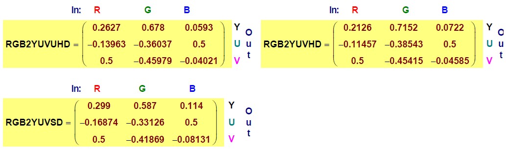
Note the U & V gain factors = 0.5 for the corresponding B & R inputs and UV White Balance (if R=G=B=1, then U=V=0). This is due to the requested mapping scheme: UV output range is [-0.5, +0.5] centered at 0.0 point.
MathCAD calculated UV coefficients with high accuracy (up to 5 digits after decimal dot). For practical applications they should be rounded to the appropriate bit depth, and it is very important to keep UV White Balance (sum of 3 coefficients in UV rows must be exactly zero).
Inverse YUV to RGB matrices require high accuracy in all 3 rows:
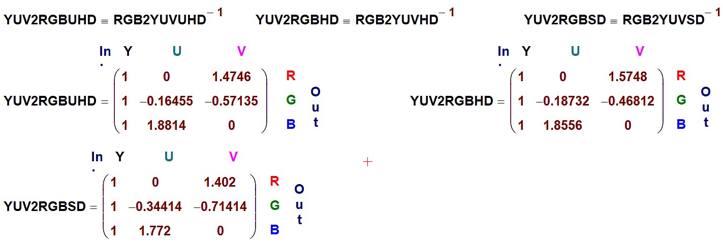
Note the Y to RGB Unity Gain factor – all 1st column coefficients in all 3 matrices are exactly 1.
Also note the U to R and V to B gain factors are 0. In other words, it means that the UV axes of YUV color pace are orthogonal and there are no cross-contributions.
Thus, the U input contributes mainly to B and not so much to G; similarly the V input contributes mainly to R with some smaller contribution to G.
It should be noted that, in practice, the selected Encoding Color Space (i.e. the selection of RGB to YUV and YUV to RGB matrices) may or may not match Camera Color Primaries and/or Display Color Primaries.
Standards define the matrix coefficients and signal levels in relative units, i.e. [0, 1] or [0%, 100%] for RGB and Y, [-0.5, +0.5] or [-50%, +50%] for UV.
Digital signals are usually defined not in percents, but in 8, 10 or 12 bit levels. Also there are two types of digital signal ranges in use: Full & Narrow.
Next image shows the generic block diagram of the RGB data to YUV data conversion process:
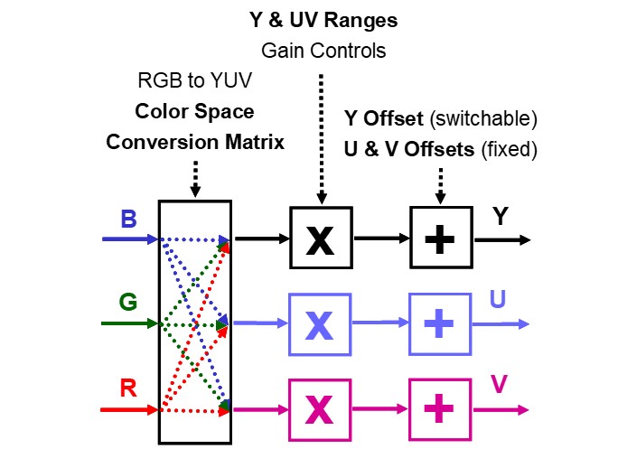
For calculation of 8, 10, 12, etc. bit digital levels it is convenient to use ubiquitous 8 bit values adjusted by the generic scaling parameter BAF:
BAF = BitDepth Adjustment Factor = pow(2, BitDepth – 8).
The coefficients used for conversion of YUV relative levels in percents to Narrow Range (aka “D1”) YUV and Full Range YUV 10 bit data levels are shown below:
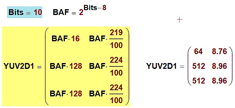
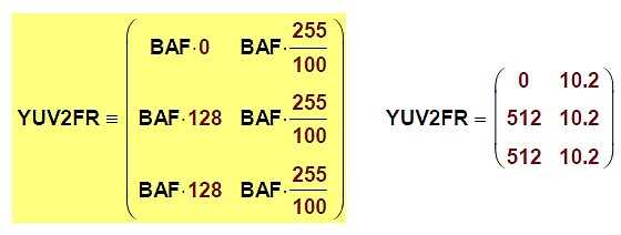
The 1st column coefficients are 10 bit offsets, 2nd column coefficients are gain factors.
These two sets of coefficients can be used for accurate calculation of digital YUV levels, e.g. Color Bars Test Pattern levels. They are suitable for any Dynamic Range format and for any Encoding Color Space.
See next:
Tables and numerical examples of reference values, such as Color Bars Reference Levels for a variety of Color Spaces.
Learn more:
See posts in the Video Science Fundamentals category.